VTX
Supra-VTX VTX 5.8G 40CH 25mw 100mw 200mw Transmitter OSD adjustable
For Brushed Bwhoop Mobula7 Mobula6 FPV Racing Quadcopter
Login to view prices
The Supra-VTX series is transmitted as a 5.8G ISM band analog image transmission. It has stable output power, long transmission distance and strong power supply filtering. It can ensure that the image has no snowflake and no horizontal stripes under the maximum throttle. With stackable mounting, it fits perfectly into the upper part of the flight controller, improving rack space utilization and greater safety. The picture adopts the flight control OSD (TXD-IRC Tramp) signal to control the transmission frequency of the picture, and only needs to connect any TXD (serial port transmission) of the flight control to the RXD (serial port reception) of the picture transmission, and also retains The function of manual button switching. Support PIT mode tuning.
Features:
1. The output power is stable and the transmission distance is long.
2. Fast 3-speed power switching, independent two red indicators, indicating the current transmitting power of 25/100/200MW.
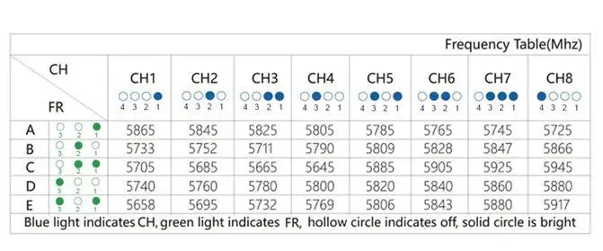
3. The frequency point uses 4*3 LEDs to display 40 channel values.
4, support OSD remote tuning (IRC Tramp), support PIT mode tuning, can only be opened in the OSD.
Performance:
1, input voltage: DC 4.5-5.2V
2. Input current: 200MW = 500 MA
3, power switching: third gear 25MW, 100MW, 200MW
4, signal channel: 40
5, frequency switching: manual button / OSD (IRC Tramp) (simultaneous support)
6, antenna interface: IPEX
7. Dimensions: 24mm*27.5mm, mounting holes 25mm*25mm.
8, weight: 2.0 g
Overall introduction:
GND power supply negative
+5V power supply positive
VIN camera video input
RXD flight control serial transmission
Frequency adjustment:
First, manual adjustment
The FR button switches the frequency.
Short press: switch channels, 4 blue LEDs indicate channels.
Long press (2 seconds): switch group, 3 green LEDs indicate group.
There are 40 frequency points, and the specific channel frequency refers to the frequency list.

Power switching:
POW button power adjustment. Press once to switch the power 25MW, 100MW, 200MW.
 red circle is light; hollow circle is off
OSD tuning parameters
1. In the PORTS of the flight control, you need to configure the TX port to be used for the OSD adjustment, and the interface needs the interface, as shown in the following figure in UART1.

Select IRC Tramp.
The first step is to properly configure the receiver to ensure that the receiver channels are normal. In the example, the OSD is used for TX1 and the receiver is used for RX6.
In the second step, put the throttle to the middle position of about 50% (THR MID), the direction lever to the left (YAW LEFT), and the pitch lever to push forward (PITCH UP). Enter the OSD menu.
The third step is to switch the VTX channel and transmit power.
On the MAIN page, select the FEATURES item and go to the FEATURES page.
Select the VTX TR option and go to the VTX page.
Select CHANNEL to switch channels and select POWER to switch the transmit power.
Select SET and select YES to make the settings take effect.

Precautions for use
1. Pay attention to the input voltage within the specified range and the positive and negative poles are correct, so as not to damage the internal components;
2. If the antenna is replaced, please select the standing wave and the antenna with good gain to obtain a longer transmission distance;
3. Pay attention to static electricity during transportation and installation;
Shipping list:
transmission module * 1
Antenna*1
Shock absorber ball *3
Wire*1


| Weight | 0.05 kg |
|---|---|
| Dimensions | 8 × 8 × 8 cm |


There are no reviews yet.